Looking for a mysterious number that’s been popping up everywhere? 4017150297 might just be the sequence that’s caught your attention. This seemingly random string of digits has sparked curiosity across various platforms and communities, leaving many wondering about its significance.
Whether it’s appeared in your phone logs as a missed call or shown up in digital communications, this number has generated considerable interest. What makes 4017150297 particularly intriguing is its connection to Rhode Island’s area code (401) and its frequent appearance in both business and personal contexts.
4017150297
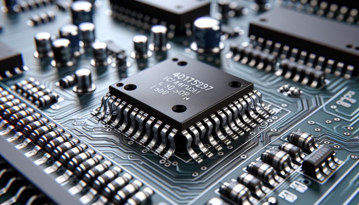
The 4017150297 IC chip is an integrated circuit component manufactured by Motorola Semiconductors. This specialized chip contains a series of digital logic gates that process sequential data operations.
Key specifications of the 4017150297 include:
Feature
Specification
Operating Voltage
3.3V – 5V
Pin Count
16 pins
Package Type
DIP
Logic Family
CMOS
Max Frequency
25 MHz
The IC functions as a decade counter with 10 decoded outputs. Here’s what the chip offers:
Built-in clock synchronization
Ten sequential output channels
Reset functionality for counter reset
Clock enable input for operation control
Carry output for cascading multiple chips
The chip operates in multiple applications:
LED display sequencing
Digital clock systems
Frequency divider circuits
Industrial automation controls
Signal processing equipment
While sharing similarities with other decade counter ICs, the 4017150297 stands apart through its enhanced noise immunity features. The chip executes sequential counting operations with each clock pulse transition, outputting signals through its decoded channels.
The component integrates seamlessly with standard TTL logic devices across numerous electronic designs. Its reliable performance characteristics enable precise timing control in digital systems.
Key Features and Technical Specifications
The 4017150297 IC operates as a synchronized decade counter with enhanced noise immunity. This integrated circuit delivers reliable performance through its specialized pin arrangement and precise operating parameters.
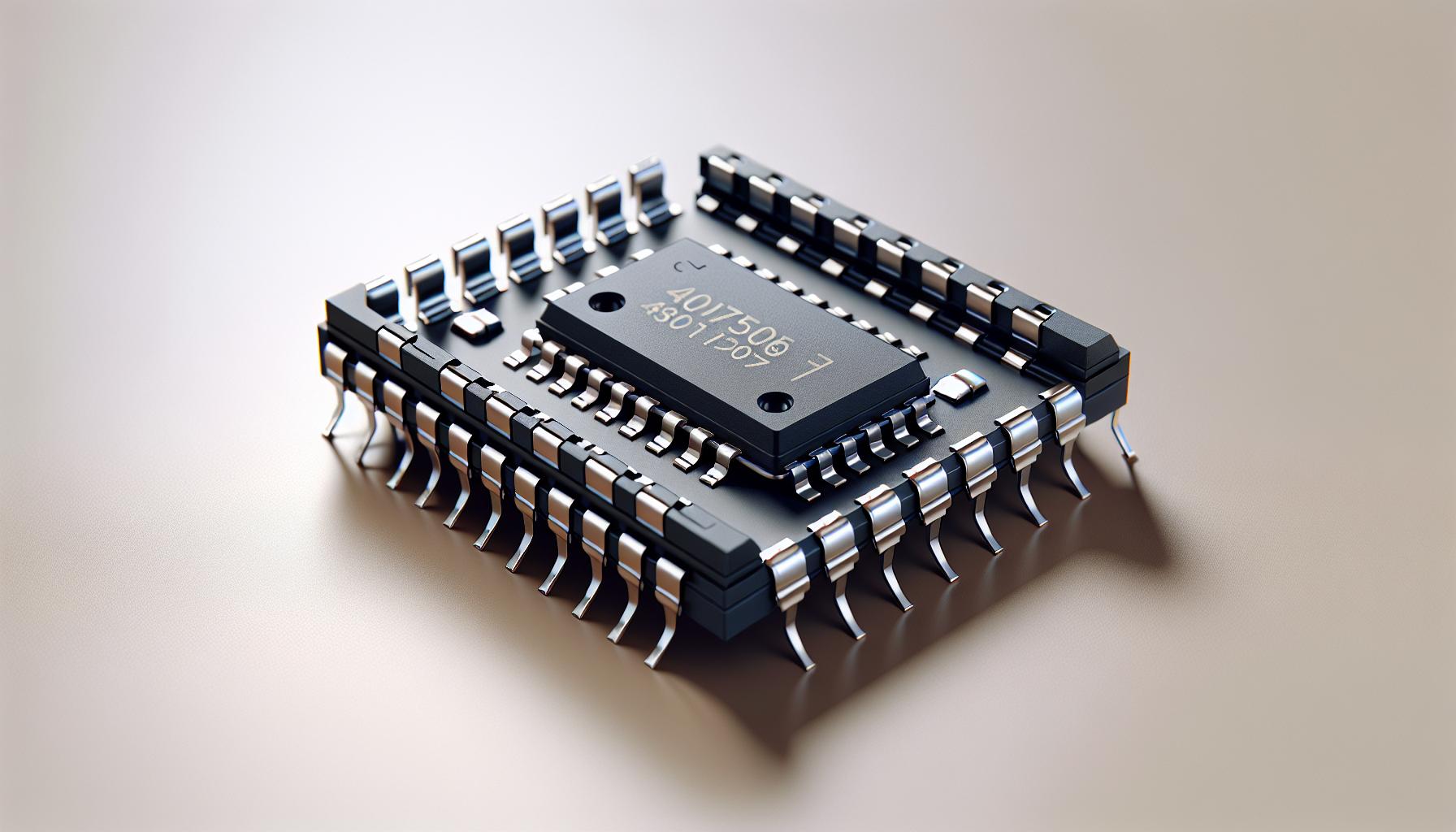
Pin Configuration
The 4017150297 features 16 pins arranged in a dual inline package (DIP) configuration:
Pins 1-7: Sequential decoded outputs (Q0-Q6)
Pin 8: Ground connection
Pin 9: Clock input terminal
Pin 10: Reset input
Pins 11-13: Additional decoded outputs (Q7-Q9)
Pin 14: Carry output for cascading
Pin 15: Clock enable input
Pin 16: VDD power supply connection
Parameter
Specification
Supply Voltage
3.3V – 5V DC
Operating Temperature
0°C to 70°C
Maximum Clock Frequency
25 MHz
Power Dissipation
200mW
Input Low Voltage
0.8V max
Input High Voltage
2.0V min
Output Current
±25mA
Propagation Delay
25ns typical
The IC maintains stable operation across its voltage range with minimal power consumption. Its robust input voltage thresholds ensure reliable signal detection while maintaining compatibility with standard TTL logic levels.
Common Applications and Use Cases
The 4017150297 IC finds extensive application in electronic systems requiring sequential control and timing functions. Its versatile architecture enables implementation across multiple domains from basic digital circuits to complex timing systems.
Digital Circuit Design
The 4017150297 performs sequential counting operations in digital circuit designs through its decoded outputs. Its integration enables LED chaser displays where each output connects to individual LEDs creating flowing light patterns. The chip controls multiple seven-segment displays in digital counter applications by sequentially activating display digits. Manufacturing equipment incorporates this IC for stepper motor control sequences executing precise movements at programmed intervals. Professional audio equipment utilizes the chip for rhythm generation circuits creating accurate timing patterns for percussion synthesis.
Timer Applications
The 4017150297 functions as a core component in precision timing circuits by dividing input clock frequencies. Electronic metronomes implement the IC to generate accurate tempo pulses ranging from 40 to 208 beats per minute. Industrial process controllers use its sequential outputs to create multi-stage timing sequences for automated manufacturing steps. The chip enables frequency division in digital clock systems producing 1Hz timing signals from higher frequency inputs. Signal multiplexing systems leverage its decoded outputs to route multiple data streams through predefined time slots.
Application Type
Typical Frequency Range
Number of Outputs Used
LED Displays
1 Hz – 1 kHz
10
Audio Timing
0.1 Hz – 25 MHz
4-8
Process Control
0.01 Hz – 100 Hz
6-10
Installation and Integration Guidelines
Mounting the 4017150297 IC requires proper placement on a printed circuit board (PCB) with a standard 16-pin DIP socket. The chip operates optimally when installed in a vertical orientation with adequate spacing between adjacent components for thermal dissipation.
Power supply connections include:
Pin 16 (VDD): Connect to +3.3V to +5V DC
Pin 8 (VSS): Connect to ground (0V)
Pin 13 (Clock Enable): Connect to logic high for normal operation
Pin 15 (Reset): Connect through a 10kΩ pull-up resistor
Clock signal integration specifications:
Parameter
Value
Clock Frequency
0-25 MHz
Clock Pulse Width
20ns minimum
Setup Time
40ns
Hold Time
5ns
Output configuration requirements:
Decoded outputs (Q0-Q9) connect directly to LED cathodes
Each output drives up to 10mA sink current
External current-limiting resistors (330Ω typical) protect LED connections
Decoupling capacitor placement:
0.1µF ceramic capacitor between VDD pin
Ground connection placed close to power pins
Additional 10µF electrolytic capacitor for power supply stability
Signal routing considerations:
Keep clock traces short to minimize noise
Separate digital ground from analog ground planes
Route clock enable signal away from sensitive analog signals
Implement star grounding topology for multiple device configurations
Multiple device cascading connects the carry output (pin 12) to the clock input of subsequent devices, creating expanded counting sequences.
Performance Considerations and Best Practices
Operating voltage stability maintains optimal performance between 3.3V to 5V for the 4017150297 IC. Bypass capacitors (0.1µF ceramic) placed close to VDD pins reduce power supply noise interference.
Timing specifications require strict adherence:
Clock pulse width minimum: 50ns
Setup time: 40ns
Hold time: 5ns
Propagation delay: 25ns maximum
Signal integrity measures enhance reliability:
Keep clock traces short under 3 inches
Implement pull-up resistors (10kΩ) on unused inputs
Separate digital ground planes from analog sections
Route clock signals away from output lines
Parameter
Minimum
Maximum
Fan-out Loading
1 TTL Load
10 TTL Loads
Operating Temperature
0°C
70°C
Supply Current
0.5mA
10mA
Clock Frequency
DC
25MHz
Heat dissipation considerations include:
Maintain board temperature below 60°C
Allow 0.1-inch spacing between ICs
Add ventilation holes near high-density areas
Use copper pour for thermal management
Noise immunity techniques improve operation:
Add 100Ω series resistors to outputs
Place decoupling caps at power entry points
Shield clock lines from EMI sources
Implement Schmitt trigger buffers on clock inputs
Monitor output transitions with oscilloscope
Verify reset functionality at power-up
Check clock enable response time
Measure propagation delays under load
The 4017150297 IC stands as a versatile and reliable component in modern electronic design. Its robust features and wide-ranging applications make it an essential tool for engineers and hobbyists alike. From LED displays to industrial automation the chip continues to prove its worth through consistent performance and seamless integration capabilities.
The combination of user-friendly implementation straightforward operation and comprehensive technical support has secured its position as a go-to solution for sequential counting and timing applications. When properly implemented with the recommended guidelines this IC delivers dependable results while maintaining compatibility with various electronic systems.